Architectural Specifications
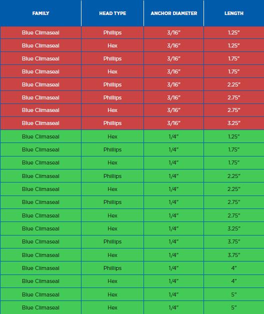
Anchor (Bolt-Down)
Bolt Lengths:
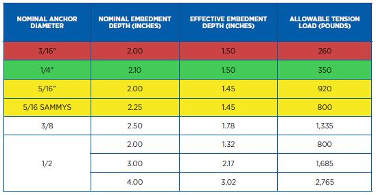
Tension and Sheer Values(lbs/kn) in Concrete:
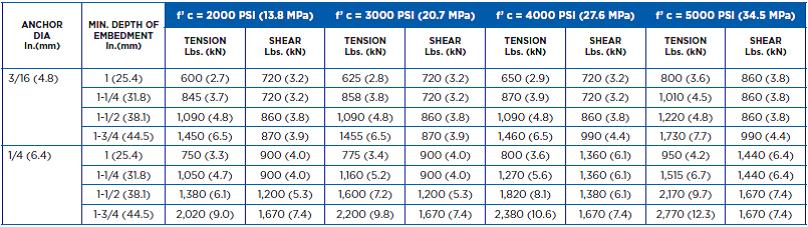
Safe working loads for installation under static loading should not exceed 25% of the ultimate loading capacity.
Allowable Edge and Spacing Distances:
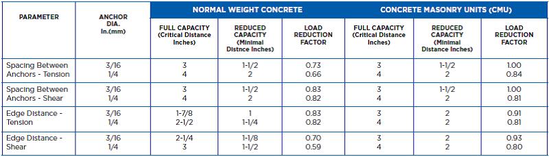
For SI: 1” = 25.4mm
EXAMPLE ALLOWABLE STRESS DESIGN TENSION VALUES FOR ILLUSTRATIVE PURPOSES FOR ANCHOR-BOLTS AND SAMMYS® SCREW ANCHOR FOR THREADED ROD 1,2,3,4,5,6,7,8
For SI: 1” = 25.4mm, 1lbf = 4.45N 1 psi = 0.0006895 Mpa
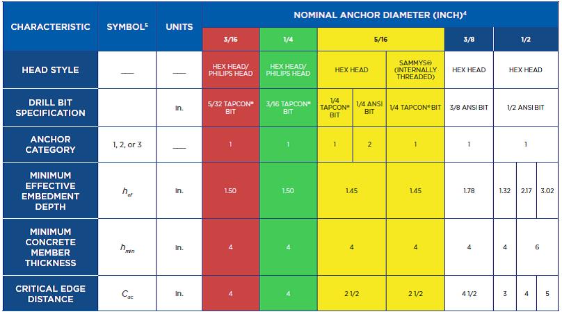
TENSION STRENGTH DESIGN INFORMATION FOR TAPCON® SCREW ANCHOR AND SAMMYS® SCREW ANCHOR FOR THREADED ROD1
Testing:
This product has also been tested in a salty spray environment for 720 hours with less than 10% red rust, per ASTM B117.
Meets or exceeds: Miami Dade #07-0315.03, ICC-ES Evaluation Report ESR-1671, Florida’s Building Code FL7556
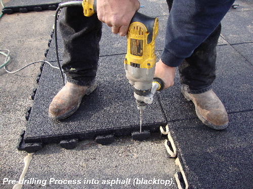
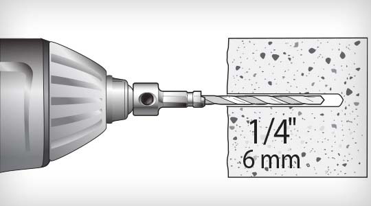
Drilling:
Drill a hole at least 1/4” deeper than the anchor embedment using a hammer drill and the appropriate drill bit size.
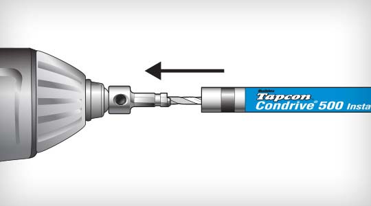
Sliding:
Slide the Condrive® Installation tool over the drill bit and snap in the drill adapter and snap into the chuck. Then place the hex or Phillips bit into the appropriate Condrive tool end. Position a 3/16” or 1/4” diameter anchor-bolt onto the end of the sleeve.
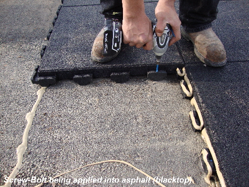
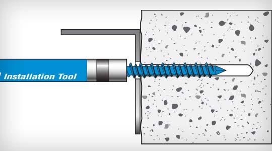
Drive:
Drive the anchor-bolt into the pre-drilled pilot hole until it is fully seated. The torque-adjusted driver prevents over-torqueing of the anchor head by automatically disengaging when it comes into contact with the fixture surface.
WE DO NOT RECOMMEND THIS PRODUCT FOR ROOFTOP APPLICATIONS WHAT-SO-EVER.